Reliable cellular connectivity is rarely limited by the router itself.
In most industrial deployments, performance issues are caused by
antenna choice, placement, and cable losses — not by the SIM or modem.
This page explains how we approach antenna optimisation for industrial LTE and
5G Sub-6 deployments, and why we deliberately avoid unnecessary or misleading
antenna solutions.
Stocked Antennas for Different Installations
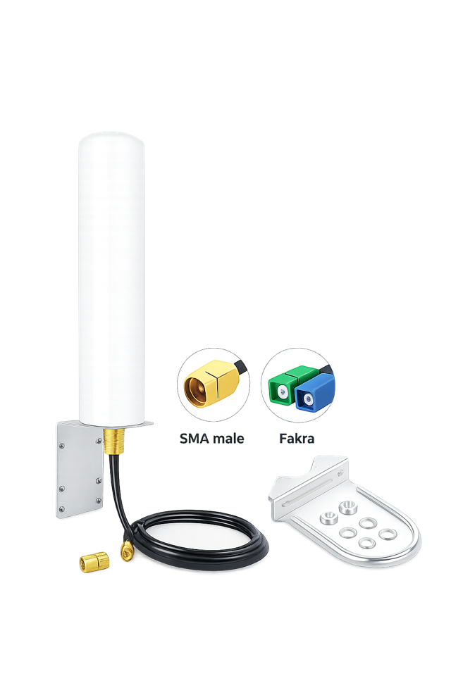
CI-OMNI-4500-RG58 is supplied with 2 x SMA male connections
Default fixed-outdoor choice
CI-OMNI-4500-RG58 Omnidirectional Antenna
For most fixed outdoor industrial 4G and 5G deployments, the CI-OMNI-4500-RG58 is our
default starting point. Its rugged pole-mounted design provides 360° coverage without precise mast aiming,
while two SMA-fed antenna lines connect to a 2×2 MIMO router.
Industrial IoT, CCTV, ANPR, utilities and exposed remote-monitoring sites
Pole mounting for fixed infrastructure in open or semi-rural locations
IP67 construction, DC grounding and specified wind resistance of 60 m/s
Supplied with two 5 m RG58 cables. Published RF measurements cover the complete supplied assembly,
including its cables and SMA connectors, without compensating away cable loss.
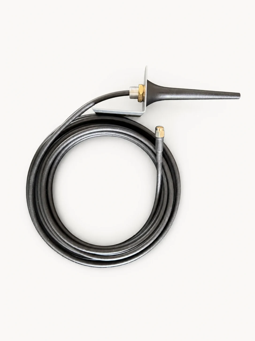
CI-MINI-3800 with metal wall bracket and one 5 m low-loss cable
Compact wall-mount option
CI-MINI-3800 Compact 4G/5G Cellular Antenna
The CI-MINI-3800 is a compact, single-feed indoor/outdoor wall-mount antenna supplied with a metal bracket
and five-metre LMR200-equivalent low-loss 50 Ω cable. It suits installations where the
router cannot be mounted close to the antenna.
Which model should you choose? Use the CI-OMNI-4500-RG58 for exposed poles and two antenna
feeds. Choose the CI-MINI-3800 where compact wall mounting and one SMA antenna feed suit the installation.
This is a single-feed antenna. A 2×2 MIMO router normally requires two appropriately specified antenna feeds;
ask us if you need help matching the antenna arrangement to your router.
Why Antennas Matter More Than Most People Expect
We frequently encounter sites where routers have been replaced,
SIMs have been swapped, or higher-gain antennas have been added —
with little or no improvement.
In most cases, the root cause is one or more of the following:
Incorrect antenna type for the deployment
Poor or misunderstood MIMO implementation
Excessive antenna cable length and connector losses
Over-reliance on “high-gain” marketing claims
Antenna optimisation is about controlling how the signal is transmitted and received,
not simply increasing numbers on a datasheet.
Understanding MIMO (in Practical Terms)
Most modern industrial cellular routers use 2×2 MIMO.
This allows the router to use two independent signal paths to improve reliability and throughput.
Typical 2×2 MIMO antenna layout
Two connectors alone do not guarantee effective MIMO
Poorly designed “MIMO” antennas can perform worse than a single good antenna
Frequency coverage matters more than marketing labels
We select wideband antennas whose documented frequency ranges match the router and network requirements.
Two connectors alone do not prove effective MIMO; antenna design, isolation and deployment still matter.
For applications requiring higher-order MIMO, we can also supply 4×4 MIMO antenna solutions
where deployment requirements justify the additional complexity.
Other Antenna Formats for Specialist Installations
Directional Panel 2×2 MIMO Antennas
Directional panel antennas are a problem-solving tool, not a general upgrade.
They are used when signal is weak or unstable and the serving base station direction is known.
Weak signal areas and edge-of-coverage sites
Fixed installations where the mast direction is known
Sites where stability matters more than headline speed
Panel antennas must be aimed correctly. Incorrect orientation can reduce performance rather than improve it.
When applied appropriately, they can significantly improve link stability.
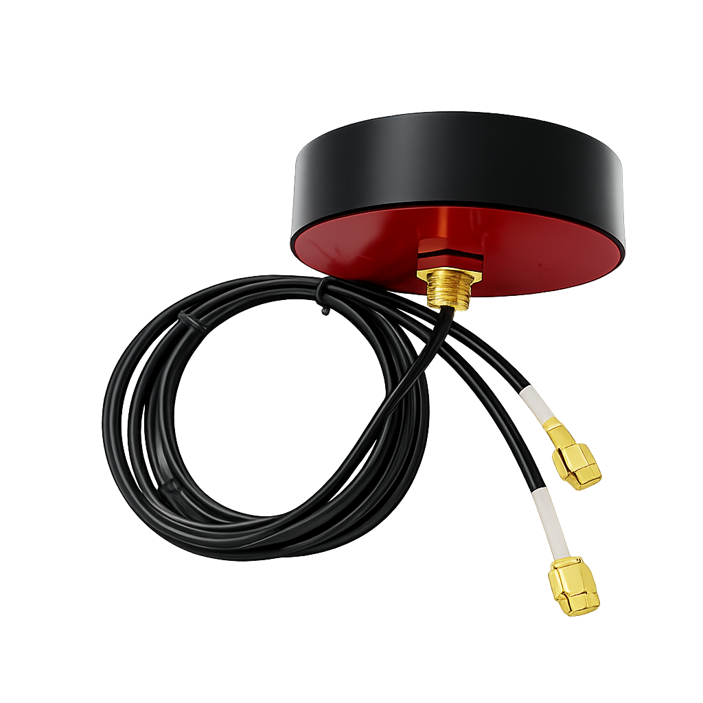
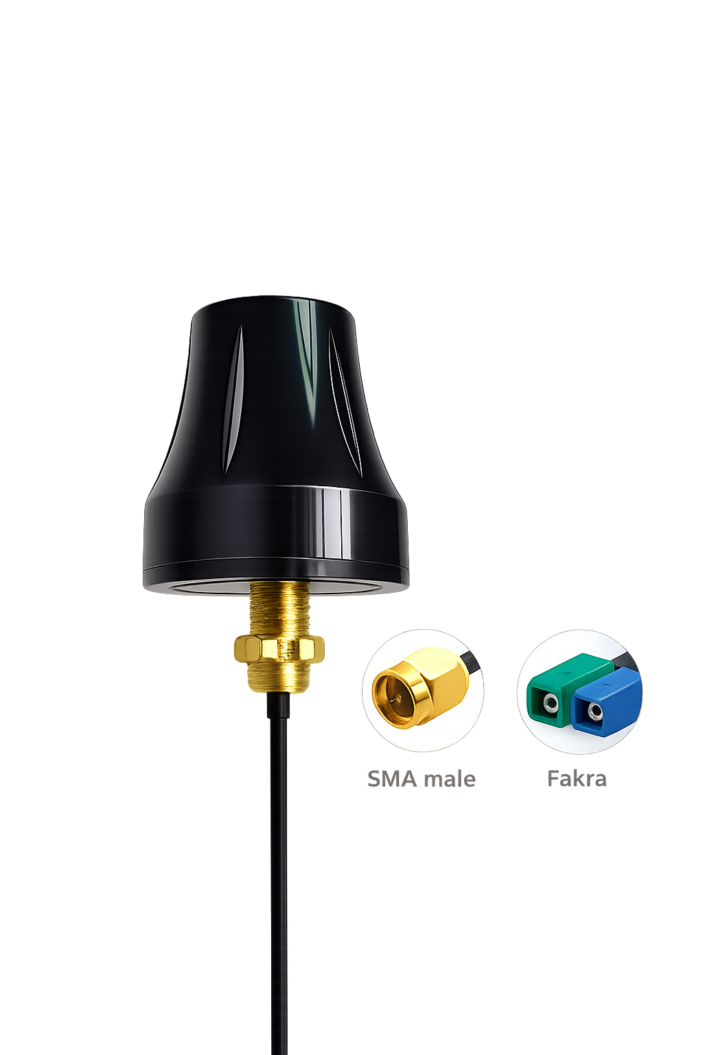
Compact Omnidirectional Antennas for Mobile & Vehicle-Mounted Assets
Compact omnidirectional antennas are used where vibration resistance, reduced-profile mounting,
and mechanical reliability are required. These antennas are suited to applications
involving vehicle motion, fleet telematics, and temporary installations where space and durability are constrained.
Fleet and telematics deployments
Service and utility vehicles
Mobile routers and temporary installs
Applications requiring reduced-profile mounting and vibration tolerance
FAKRA connectors are used in vehicle environments for mechanical reliability and industry-standard compatibility
with mobile router systems. SMA connectors are typically used in industrial or fixed installations.
With matched 50 Ω components and correct installation, connector format is primarily a mechanical choice,
although cable and connector quality still influence loss and mismatch.
These antennas are not automotive OEM "shark-fin" replacements. They are industrial RF antennas designed for
robust connectivity in mobile environments, not aesthetic integration.
Connector Selection (Practical Summary)
Antenna connectors are chosen based on deployment environment and mechanical requirements, not marketing preference.
SMA — standard industrial RF connector. Used in fixed installations, cabinets, and general industrial deployments.
FAKRA — automotive-grade RF connector. Used in vehicle environments for mechanical reliability and vibration resistance.
M12 — not used for RF antennas. Reserved for power, Ethernet, and fieldbus connections in industrial systems.
Assuming correct impedance and cable selection, connector type does not affect RF performance;
it is selected for mechanical compatibility.
Using the correct connector for the deployment environment reduces installation issues and improves long-term reliability.
Common Antenna Myths
“Higher dBi always means better signal” — false. Gain reshapes radiation; it does not create power.
“Outdoor antennas always perform better” — not automatically. Placement, obstructions and cable loss determine the result.
“Unnecessary cable extensions are harmless” — false. Every added cable length increases loss at LTE and 5G frequencies.
“Any MIMO antenna is future-proof” — false. Frequency range and antenna design determine longevity.
Our Approach
We deliberately avoid offering a large catalogue of antennas.
Instead, we focus on a small number of validated, wideband solutions
that align with real deployment conditions, avoiding oversized, narrowband,
or marketing-led antenna designs that do not translate into real-world performance gains.
For most fixed outdoor projects, we begin with the CI-OMNI-4500-RG58
and specify an alternative only when the mounting environment, cable run or RF conditions justify it.
Match antenna design to router architecture
Minimise cable losses wherever possible
Avoid unnecessary complexity
Select antennas that remain relevant as networks evolve
When Antenna Optimisation Adds the Most Value
Connectivity is unstable or intermittent
Signal readings are inconsistent
Deployments operate in challenging RF environments
Previous antenna changes have not improved performance
In these situations, the solution is rarely “a bigger antenna”.
It is the right antenna, correctly deployed.
Discuss Your Deployment
We keep a broad selection of industrial cellular antenna types available for single installations and
multi-site roll-outs. Contact us with your router model, mounting location and required quantity so we can
confirm compatibility, current availability and practical deployment requirements.